DAMON JURKIEWICZ
CNC FRANKEN-MILL PHASE II
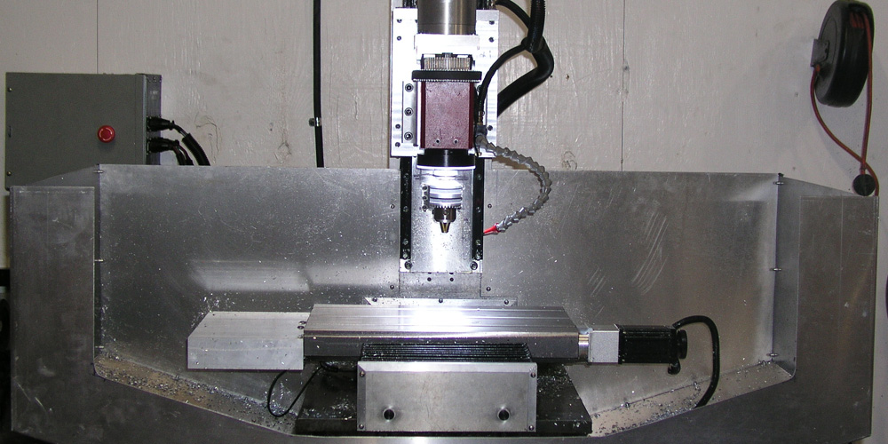
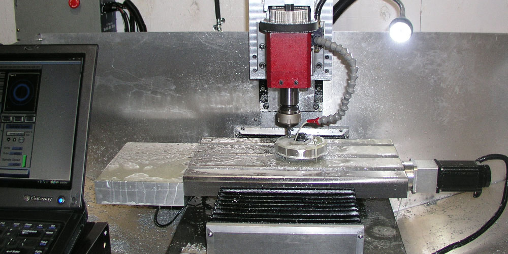
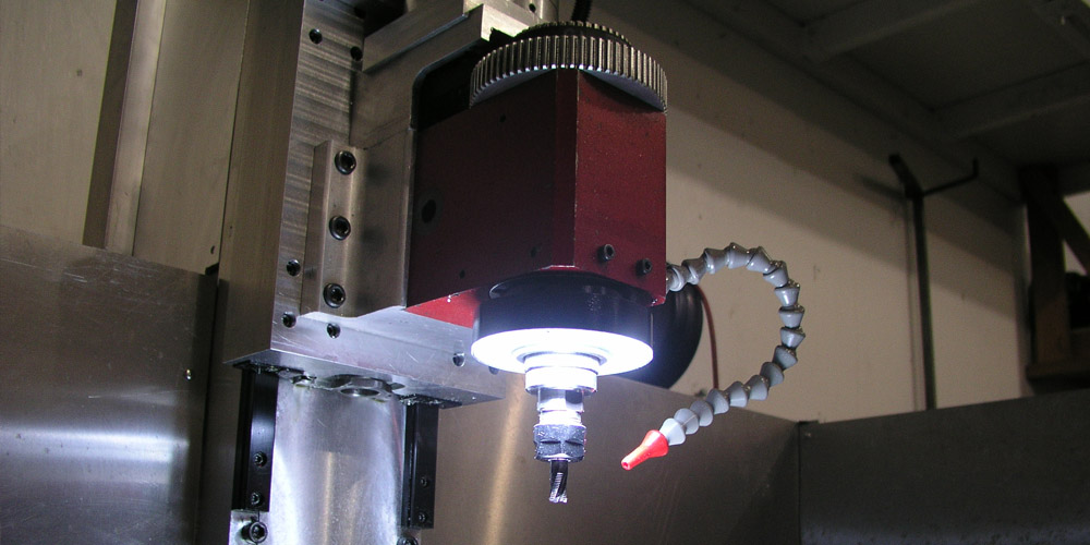
Welcome to Phase II of the Franken-Mill project. I have a lot of updating and uploading to do to get this page caught up with the current status of the machine. As of 4-13-14 we are live and devouring all sorts of billet materials! A quick run down of the final project: The machine has an envelope of 10 X, 8 Y, and 9.5 Z. The head is fully counter weighted and now features a 2.8 HP DC variable speed drive sourced from an old treadmill and a spindle supported by precision grade angular contact bearings. The spindle runs in two speed ranges, 0-1500 RPMs and 0-6000 RPMs using a GT profile belt drive with 4:1 and 1:1 pulleys. The 4:1 reduction gives the system amazing torque and the ability to run large diameter end mills. All sliding surfaces and motion components are fully pressure lubricated from a central oiling system and there is now flood cooling and cutter lubrication with a return sump and 250 GPH pump.
At present I have tested the machine with a .75" cutter running at 1500 RPMs with a feed rate of 20 inches per minute and a cut depth of .125 inches. The results were pretty amazing for such a small machine. More impressive were the test cuts at 6000 RPMs with an extended length die sinking .125" ball mill. Look for that photo in the slide show. The finish was perfect with no chatter what so ever.
The video below shows the mill running at 6000 RPMs with a two flute 3/8" end mill making a .075" deep cuts at 75 inches per minute. Make sure you turn up the sound!
First movement on its own, first auto homing cycle.
Testing at 75 inches per minute feed rate and 6000 RPMS
Column and Head Re-Construction Process

It was obvious that the Z axis dove tailed slide that I adapted from a Chinese X2 mini mill was really holding back the true potential of my first CNC milling machine for more reasons than I am prepared to list. So I began to rethink the machine. First off I wanted to use pre-loaded precision linear slides instead of cast iron dovetails. That would resolve issues of friction, head droop and lubrication on a vertical surface. Counter weighting of the head was also a desired modification, this would greatly improve vertical high speed profiling performance and reduce the load on the Z axis stepper motor. Lastly I was looking for rock solid vertical column rigidity. This would prove to be more of a challenge than I had anticipated especially since I was trying to recycle as much content as possible from the existing machine.

I started with with some large 6061 T6 aluminum box tubing. My plan was to laminate additional tubing inside to increase the rigidity of the column. So I thoroughly scuffed, roughed and cleaned everything to prepare for the bonding process.

So some of you are probably questioning my approach here. Who would possibly use laminated construction on a milling column? Well I bonded a lot of formula cars together over the years and they worked out pretty well. Jets also use a lot of "glue", another successful bonding example. So I'm using the same material here, aircraft structural epoxy.

After laminating I went over to a friends shop to use his LARGE vertical mill to square up the new column. Contrary to popular belief, extrusions are NOT flat, straight or square.

Squaring process, the sharpie marker glyphs on the side are the initial measurements showing the bow in the column. This is being corrected through flycutting.

After flattening the column within .0005" I cut register pockets to positively and squarely locate the ball slide assemblies.

Drilling the linear slide bolt holes.
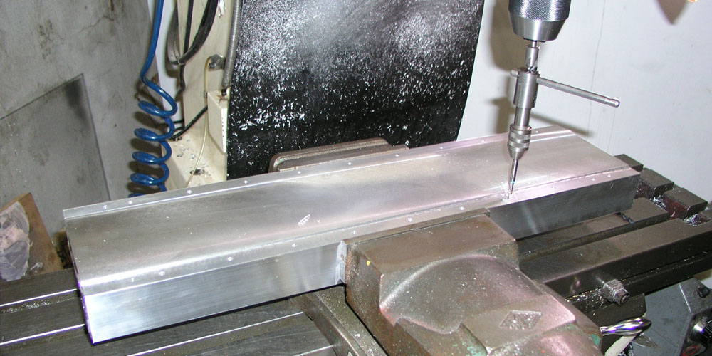
Back at the ranch using my vertical boring mill I went about tapping all the linear slide mounting holes.

Here goes the first linear slide test fit up.

I decided that making the column stiffer at this point couldn't hurt. I added a pair of cold rolled high carbon steel bars to the column. Here I am squaring and sizing them.
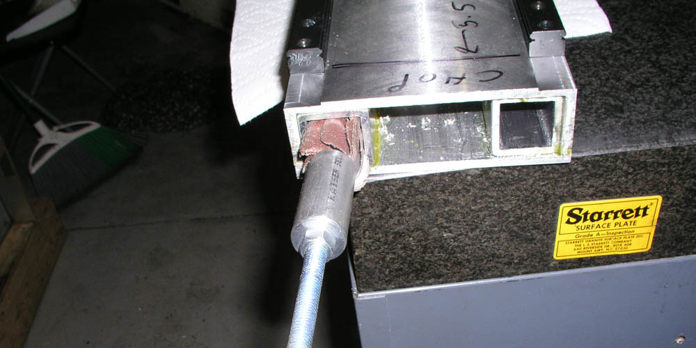
Once again cleaning and roughing the surfaces for the bonding process. I should have just used bigger steel bars from the start instead of the aluminum inserts.

Getting ready to insert and laminate the steel bars. For this operation I went with good ole JB weld. It has enough viscosity to fully coat and maintain a uniform thickness around the bars while it sets and cures. JB weld is truly one of the world's wonder substances.
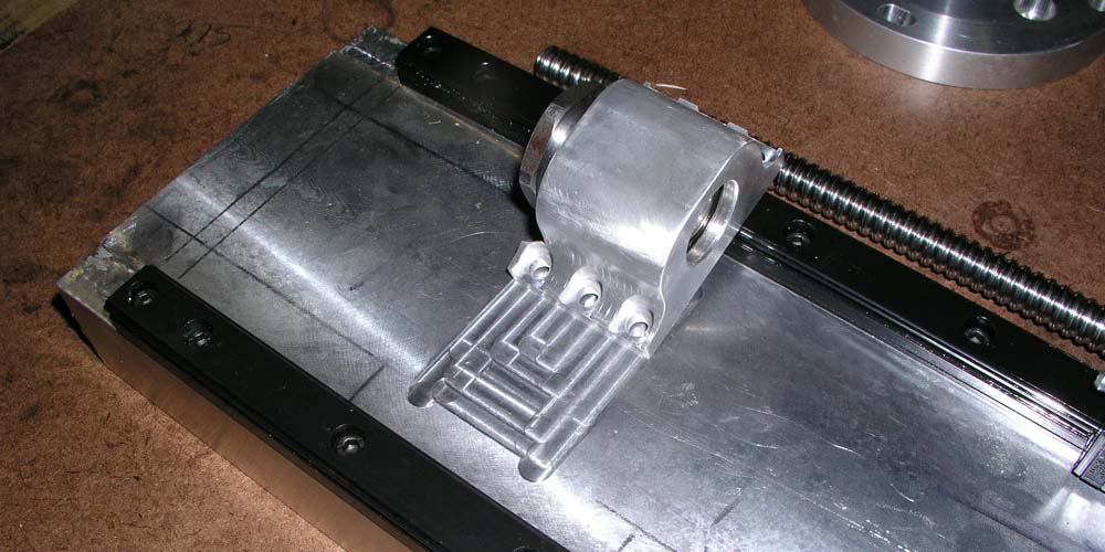
I recycled the old Z axis support bearing for the new Z axis. It has been shaved and sculpted a bit to reduce its size. The block is a light press fit into the pocket to ensure stability. The pocket allows for lateral movement to make fine adjustments before bolting and pining everything together.
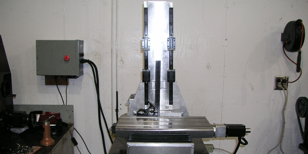
A quick test fit of to see how things are looking. The 12 inch scale should give you an accurate idea of the size of the new column. Twice the width of the old one!

With the column coming into focus I started on the Z axis saddle. This began as a massive chunk of Ebay sourced surplus aluminum billet. Remember when it comes to machine tools mass is good because it absorbs and dampens vibration.

Without changing setups, I attached a horizontal milling head to profile the underside to clear the Z axis lead screw bearing mount. Horizontal heads are a useful trick.
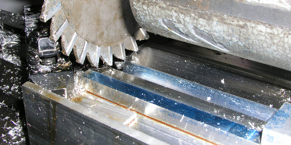
Chomp chomp chomp! A side cutting saw is an effective weapon against aluminum slabs.

Beautiful! We are ready to move this over to the horizontal mill for jig milling and boring the ball nut pockets.

Just a quick check to see how flat and parallel things are. The part is holding .0005" over its 10" length and 7" width, I can can live with that.

The first step in squaring the block for processing on the horizontal mill, I use a test bar to establish a rough zero position then dial it in with a .0005" reading indicator.

Using a 1 1/2" end mill to make a plunge cut for the ball nut body.
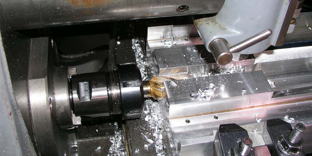
Once more I will point out that this is kind of operation is a lot easier on a horizontal milling machine. Gravity is helping the chips out of the hole! Vertical mills require a blast of compressed air or flood coolant to keep the chips from packing up in your work piece.

Now we go in with a massive shell mill to cut the flange mount pocket for the ball nut.

Horizontal mill wins again! Try that on your R8 spindle Bridgeport!

So here is the parts pile as of 10-26-2013

And this is where the assembly is headed.

Here's another view of the mocked up Z axis assembly.

Right now the machine will have about 8.25 inches of throat clearance. In order to place the center line of the spindle over the center of the table travel we will be adding a new spacer plate under the head flange that will move the throat distance out to 9 inches. With 8 inches of X axis travel there will be plenty of room for work to move around under there without running into anything.

Skipping a few steps... because I didn't take pictures... This is the head and spindle ready for assembly. The original Chinese made RS series deep groove bearings were pretty trashed due to being crushed on installation or somebody over tightening them at some point. Remember the head was a used recycled part with an unknown past.

I decided to try using high precision tapered roller bearings in the spindle. In order to accurately adjust them it was necessary to lightly polish the shaft for the upper bearing so it is a light press fit which will allow me to set the pre-load using the spindle lock nut. Be sure to measure before you go crazy with the emery cloth.

This is what are looking for, a nice light press fit.

The lower spindle bearing is still a press fit, a tight one. 20 ton press style. Make sure to protect the spindle nose with an aluminum block to prevent any damage and support the back of the bearing with an old bearing race is you happen to have one around.

This is installed bearing orientation.

Timken race installation. Make sure everything it totally clean and dry before beginning this process

Spindle installation goes like this. I am using MAGNALUBE (http://www.magnalube.com) PTFE fortified synthetic grease. McMasterCarr sells it. The stuff is excellent, very high temp, very low viscosity, waterproof, indestructible and pretty much the best stuff I've used as a general purpose grease. Makes awesome spindle and ball screw grease.

In order to get the drive key back in the spindle for the drive pulley you need to step it to fit under the bearing race.

Mostly assembled head with 72 tooth lower pulley attached, wave washers installed to equalize the bearing nut tension and the bearing nut holding it all together.

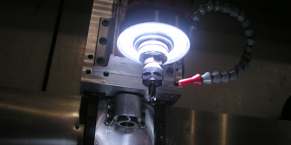
Adding the spindle nose protector / grease seal / LED ring light mount. Keeps dirt out, keeps grease in.

I let the grease seal center the nose by leaving enough float around the fasteners as well as the flange. This ensures equal loading. The light has a pressed and glued polycarbonate lens I made on the lathe that features a fine thread center hole. Using an o ring at the base and an o ring at the lens I am able to completely seal the light once it is threaded on to the nose. The o rings provide enough compression that I can "time" the location of the power cable.

This is how the upper pulley attaches. It actually has a very light press fit into the large pulley and the three small screws prevent it from coming loose. This gives me a 1:1 and a 4:1 ratio for this machine or 6000 and 1500 RPMs respectively. Good insurance against a stalled cutter at lower speeds. Look for awesome deals on GT and High Torque Drive pulleys on EBAY. Otherwise there is always Stock Drives https://sdp-si.com/eStore/Catalog their free online belt and pulley calculator is extremely useful.

Installed head and drive system looks like this.

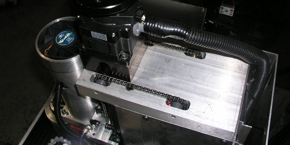
So the next step in this adventure was to seriously upgrade the drive system. The Mini Mill motor and controller just don't have enough beans to get the job done reliably without a stalling incident. You can very easily find new and used treadmill motors and controllers on EBAY for very reasonable prices and they are amazingly powerful for the money. This motor is rated at 2.8 HP @ 130 VDC or 2.6 HP continuous @ 110 VDC. Buy a used MC-60 treadmill motor control for $30 and you have bulletproof combination. This picture illustrates the motor after I began the process of ripping it apart, rebuilding it and creating a mount. On the right you can see the freshly turned commutator. What I didn't like about this used motor was the cheesy bakelite plastic top bearing carrier and brush holder combined with the cheesy pressed steel lower bearing carrier. So I improved it!

The first step was to adapt this heavy duty die cast brush housing and bearing carrier to fit the motor. The aluminum has far better heat transfer properties greater strength and superior dimensional stability than its thermoset plastic counterpart.

This is the process of re-machining the end bell to fit the back iron of the motor. Pretty simple process if you happen to have a vertical boring mill with an auto feed boring and facing head at your disposal. Much easier than trying to do this in a lathe!

I made a new lower end bell out of billet, this component started on the lathe. This shows the armature bearing final test fit.

With the end bell roughed out on the lathe it was time to add the rest of the necessary details namely tapped holes for the two motor studs and ventilation slots. The Ventilation slots were pecked out using a short NC spotting drill, AKA plunge roughing. A very effective way to reduce machine time.

Here is a quick overview of the ventilation slot milling process using a rotary table.

The part goes back on the lathe after slotting and drilling so it can be turned to its final dimensions. Watch as the slots magically appear!

Pretty clear difference in between the original parts and their aluminum replacements.

Most people don't know this but you can set the timing on an electric motor just like the engine in your car! I played with advancing and retarding the motor to get the right balance of RPMs and torque at my target voltage. In this case you are moving the magnetic field in relation to the motor brushes.

Here is the installation of the motor in its new sliding mount bracket. The motor was press fitted into the bracket and fixed in place with a set screw.

Some other critical aspects of the motor are the controller and the forced air cooling system. The control board is an MC-60 tread mill motor controller which is easy to find on EBAY and very easy to hook up. It can be controlled directly using a potentiometer or you can interface it to Mach 3 with a inexpensive board from cnc4pc.com. The "cooling tower" has a 150 CFM fan in the top drawing cold air through the windings and brushes as well as air around the motor back iron itself. Obviously I need to clean up the conduit management going into the motor housing.
Check back soon for more mechanical mayhem!
Updated 4-16-2014
