DAMON JURKIEWICZ
CNC LATHE PROJECT
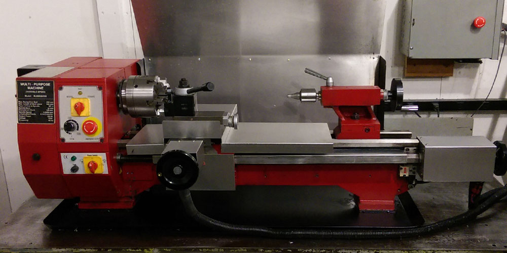
This machine was initially purchased as a functioning CNC mill/lathe combination "prototype" from a product developer on the west coast. After a short time of ownership I made the decision to tear the machine apart and redesign the entire motion control system. At the same time I began to build a dedicated milling machine from the vertical column. That project can be found here.
Getting Started: Rethinking The Cross Slide

This is the CAD model for the redesign of the cross slide using a much larger ball screw. There are also three deep groove bearings in either end of the assembly with a light preload and disc springs to eliminate end play due to thermal expansion.

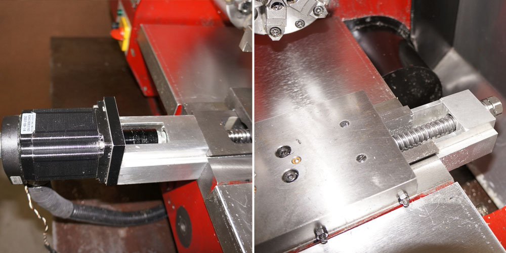
I started by running a reamer through the screw bore to add just a little more room and clean up the casting flash.. Next I plotted out how to add a 16MM flat mount ball nut to replace the tiny 10MM ball screw assembly that the previous owner had employed. You can see the comparison on the right.

Next we put the saddle casting on the milling machine and mill out just enough space to clear the ball nut.

As you can clearly see this is a tight fit at best but I felt that a screw smaller than a 1605 was going to be too small.

This is the process of making bearing support blocks for the front and rear cross axis support bearings.
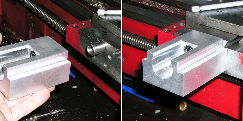
Test fitting things before making some final adjustments. The bearing support block is a light press fit onto the hollow locating dowel for perfect axial alignment.

I'm reusing the old mounting hole pattern on the front of the machine rather than tapping and drilling more holes in the cast iron saddle. The bearing block is being surfaced flush with the top of the cross slide dovetail. On the right, that's a MONSTER toolmaker's vise I found on sale. I much prefer it to a Kurt. Square within .0002"!!!
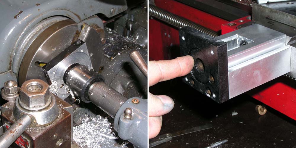
I recycled the old stepper motor mount but added a concentric locating feature on the back to ensure perfect alignment with all the other components.

And here we have the fully assembled saddle/cross slide unit ready to install.
Rethinking The Z Axis Motion Control

My next task was rethinking the main lead screw. I decided to reuse the original factory lead screw bearing blocks from the manual lathe. My first job was to bore them out and fit them with three sets of deep groove bearings each. Next I salvaged a new/surplus 20MM ballscrew from linear stage I found. The screw had backlash compensating double ball nuts, a great choice for a CNC lathe leadscrew. I should point out that the original screw I replaced was only a 16MM. Small for this application.

Here are the finished screw mounting blocks.

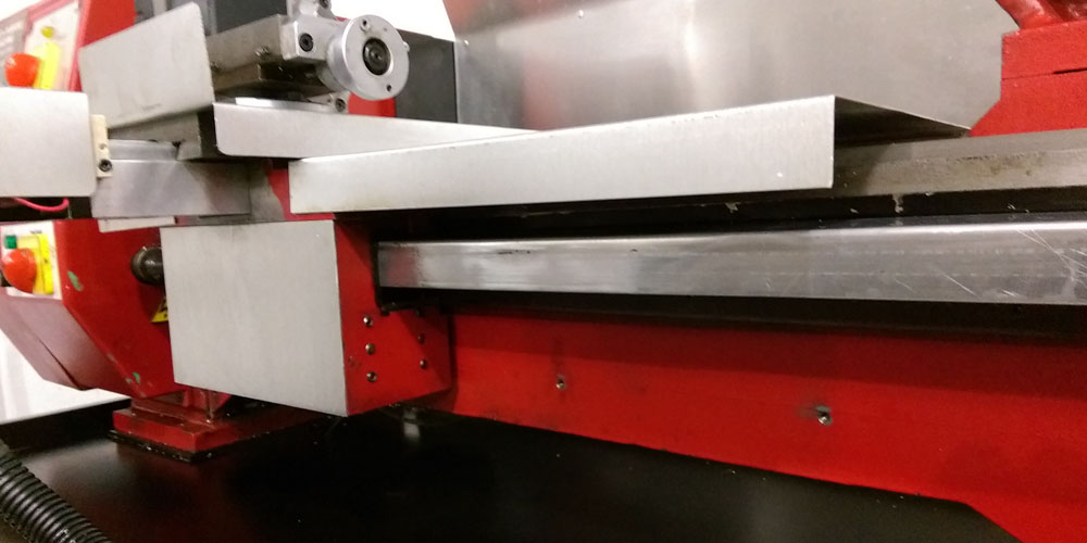
This is the process of modifying the saddle apron to fit my new 20MM lead screw and the formed screw cover to keep it free of chips and contaminants.
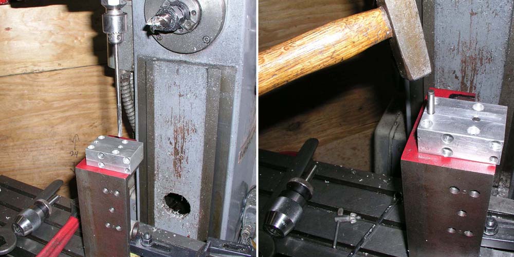
This wasn't the cleanest mounting solution but it was the most practical. The external ball nut mounting block allows me to align the nut and employ a protective screw cover. Once aligned and located the block is pinned in place to ensure that it doesn't ever move.

This shot was actually taken during the fitting and measuring process but it lets you see just how all this goes back together. Like I said, the external mounting block wasn't the most beautiful solution but it proved to be effective and easily accessible. Once the cover is screw fitted you will barely even see any of the screw mounting assembly.
Adding a Six Jaw Chuck

I found a beautiful 5 inch six jaw true adjust chuck for sale and decided that this machine REALLY needed one. The only problem is the total lack of dedicated spare parts and accessories for this particular lathe in North America. I was able to shake the parts department down at Grizzly for the mounting studs but I was totally on my own to make a true adjust style back plate. So I ordered a blank back plate along with the chuck and hogged it out to fit .
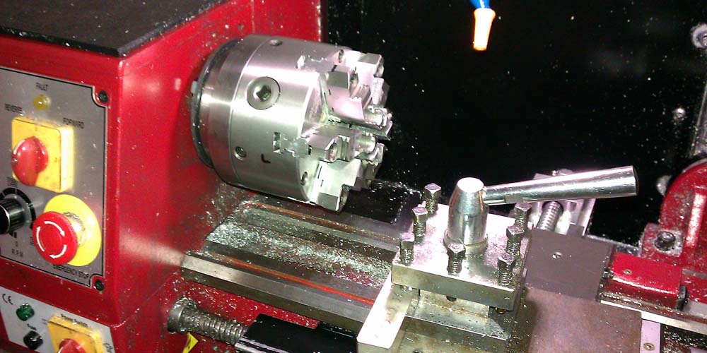
Here is the fitted chuck. One of the nicest Chinese made machine products I have seen yet. Apparently a couple of guys from Bison started a factory in China and these are the chucks they are now producing. Beautiful and REALLY accurate. I have no trouble holding .0005" run out with this thing.
Central Oiling System

Under the cross slide protective cover lies a maze of lines and fittings.

The lines come off the back of the saddle from a central lubrication distribution manifold. The fittings are tapped into oiling to the galleys for the cross slide and bed ways.

Detail of the central oiling manifold located on the rear of the cross slide.

Automatic lubrication pump that starts with the power switch for the lathe. It is fully programmable for frequency and duration. This feed the manifold through a flexible line.
Updated 02/08/2016
