DAMON JURKIEWICZ
CNC FRANKEN-MILL PHASE 1

This chronicles my first attempt to assemble a stand alone CNC milling machine from a pile of spare parts, a lot of eBay sourcing and a bunch of in house machining. The main objective of this exercise was to spend as little as possible and recycle as much as possible while creating a reasonably accurate piece of equipment. Most people would have been happy with the resulting machine, however, I live in a world of .0005" accuracy and not .003" accuracy. The potential of the machine was severely limited by the X2 mini mill spindle and drive system along with the short contact length of the X2 column, but it worked well enough for a few simple projects and proved to be a great learning experience.
I revisited this project later to make some major improvements to the column and head which you can find here. CNC FRANKENMILL PHASE II
Follow through the process as I go insane building a 4 axis CNC milling machine from the spare parts bin!

This is as good a place to start as any. I stumbled across a crazy close out deal on a brand new XY table with 8" x 10" capacity. It was also built like a brick sh!t house as they say. Sitting below it is an old school precision hand flaked iron surface plate I found locally for $50. They fit together pretty nicely don't they?

This component was actually recycled from a previous project, this is how it was made. The large fabricated angle plate is being created from surplus precision ground aluminum tooling plate. Notice that it is being cut on a horizontal milling machine, a tool every machine shop should own in addition to a vertical mill. Look how easy it is to fixture a part for peripheral machine work.

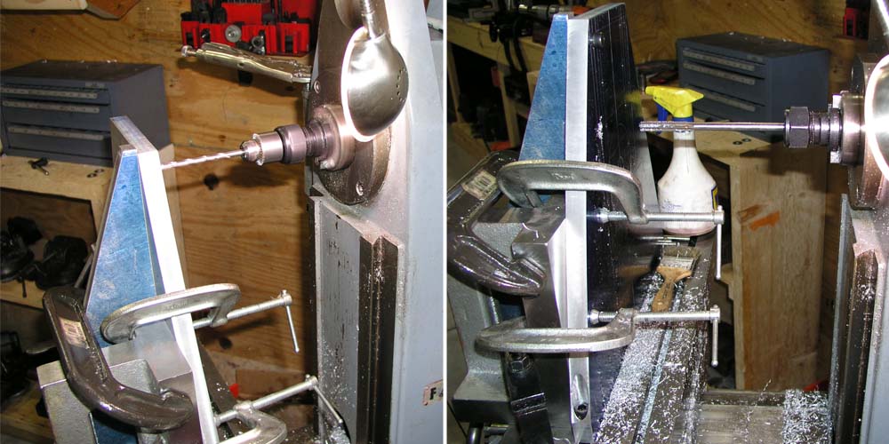
Once again horizontal mill wins! Jig drilling, tapping, reaming and pinning the angle plate together using a precision angle block as a fixture.

So are we beginning to see why a horizontal mill is handy? Final squaring of the angle plate and jig drilling the base.

Finishing up the angle plate and counter boring the socket head cap screw pockets. Checked out against the .0002" flat/square precision angle plate we look pretty good.

This is how you create a self tensioning, self adjusting ball screw assembly. By replacing the ground preload shims with disc springs it is possible to create constant tension between the two opposing ball nuts. As a bonus, the assembly can deal with changes in temperature and maintain zero backlash even if the screw wears sightly. In this slide I am slotting the disc springs with a cutting disc so I can reinstall the anti rotation fingers.

Assembling and disassembling ball screws requires a magic tool. I made one on the lathe using a small piece of aluminum tubing. The alternative is tiny ball bearings all over the floor that you will need to count and then repack by hand. I don't recommend that method.

Shown here I am making the support bearing block for the Z axis. It so happens that I had a radius cutter that was just the right size to finish one of the bores if you were wondering why I was using it to make a hole. That operation is followed by the use of a monster fine thread tap to cut threads for the bearing lock nut.

Here we are a few more steps into the bearing block. CHECK OUT THAT FINISH!

Here is the bearing lock nut about to be finished on my lathe and the final bearing block assembly about to be assembled. I am using sealed, preloaded, double row angular contact bearings for this application. They save time, work great, are inexpensive and a lot easier to manage than standard non sealed angular contact bearings.

The next item on the Z axis is the spindle. I am recycling the head from an X2 mini mill but it needs some modifications. With the X2 there is no way to square the head, a really serious design defect. So I'm changing that and adding some throat depth in the process.

Roughing out the Z axis modifications.

Mid process shot of the Z axis modifications.

Counter-boring and attaching the spindle mount.

Attaching the ball screw to the Z axis saddle. The previous owner of the mill column had cut the slot through the saddle casting for a screw, really bad practice from an engineering standpoint. Totally weakens the casting. I was able to strengthen it with a little ingenuity and a shrink fitted dowel pin through the an existing cross bore.

Z axis final installation close ups.

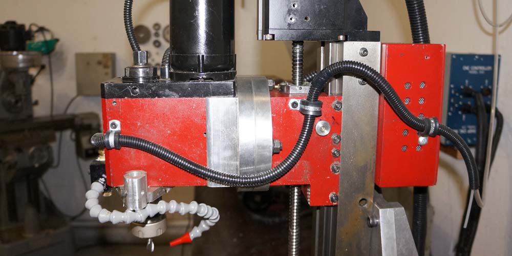
Completed and installed Z axis head and ball screw assembly. This is a later view of the head, you can also see a mist coolant system and pencil engraver attachment.

The XY table process begins with cross drilling the saddle casting for centralized oiling and plumbing it with press lock fittings. Cheap, easy, effective, and fast! This will be plumbed to a small electric pump to provide constant oil flow to all sliding surfaces while the machine is running.

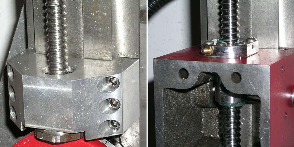
Here is a view of the ball nut mount for the compound saddle. I needed a way to distribute grease to both sides of the saddle and I decided to use the nut mounting block as a grease passage. There is a galley through the saddle casting that carries grease to the nut mounts. The little pocket in the bottom of the nut mount carries grease to the fitting, this is then plumbed to the ball nut grease fitting. All of this allows me to automatically grease the machine from one point using an electric pump.

Next up I mount the base of the XY assembly to the cast iron surface plate. The XY base has been centered and aligned to the surface plate and it is being drilled, tapped, reamed and pinned into place. I also bored two huge drain holes right in the center of the assembly to provide drainage and assembly access.

Here goes the final assembly process starting with our pile of thoroughly cleaned parts. On the table I recycled the stock screw mounts but I am using a pair of precision thrust bearings with an RS deep groove support bearing to center the screw. This is more or less how a Bridgeport table screw is mounted.

Assembling and plumbing the compound assembly. Things are pretty tight... You may be laughing about the use of clear tubing and plastic fittings in this application but they worked great, are chemically compatible with the synthetic grease and well withing the pressure ratings required for the application.

XY assembly ready to mount. Look closely and you can spot the green synthetic Teflon grease pumped in through a central fitting.

The base cabinet for the mill is a Harbor Freight closeout (somebody lost the key), with a billet top plate, a baking pan from Gordon Food Service and a universal sink drain kit that leads to a basin in the top drawer. This will allow me to have a recirculating cutting fluid system for the machine.

The surface plate literally requires an engine hoist to move, it is HEAVY. But mass dampens vibration so heavy is good! It also sits on three large rubber isolation mounts. Shown on the right side is an earlier test fitting to demonstrate how the whole thing is anchored and pinned together.

Details of the stepper motor mounting. I bought some inexpensive NEMA 23 stepper mounts on Ebay and adapted them to my needs. These are 625 inch-ounce bi-polar steppers, they should be total overkill for this application. Overkill is always better when it comes to automation.

Here is the machine in the final stages of assembly showing it with and without way covers.

Look at all that beautiful clean oil flooding the sliding surfaces! Under the protective covers this is what it looks like. The central oiling system works perfectly and should keep the machine from wearing out for a long time to come.

Here we are up and running using Mach3 and a USB connection to my laptop! All four axis are working. The machining envelop is 8 x 10 x 11.

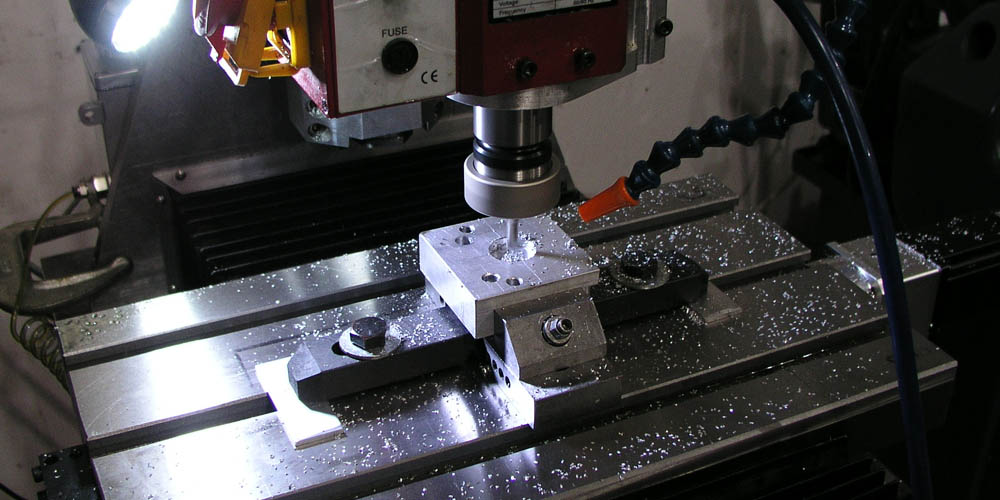
Here are some of my first test parts to come off of the machine. This piece is in 1/4 scale cut with a tiny ball mill at very high speeds. The final part shown on the right was very lightly burnished with a soft brass jeweler's brush. That was the extent of the post CNC finishing to produce the surface shown.

These large diameter flanges were produced for HS Tuning to be used on a turbo charged intake system.
I'm now working on some MAJOR improvements to the Z axis found here.